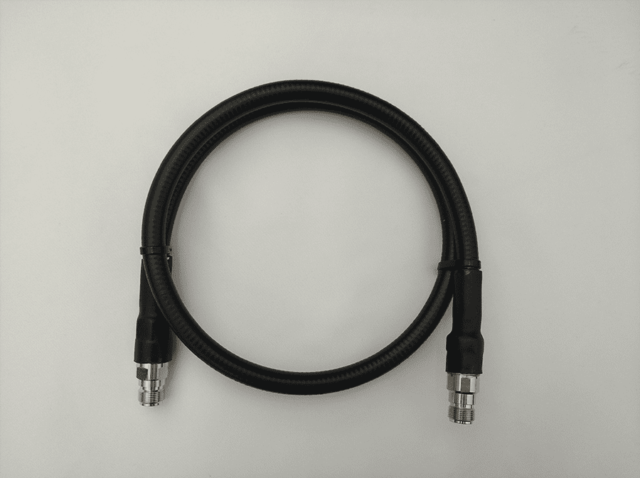
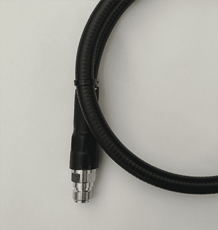
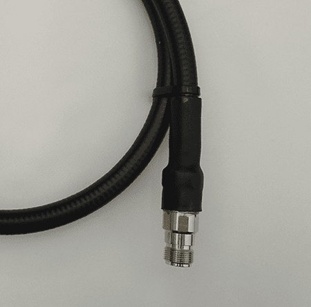
RF JUMPER CABLE [HF NF-NF]
RF Jumper Cable Coax, 1/2″, High Flex, Low Loss, N-Female To N-Female, 50 ohms
SKU: 0211-1121
| • Product Name: | 1/2” RF Jumper Cable |
| • Connector Type: | N-Female To N-Female |
| • Compliance Standards: | IEC60169, VG95250, EN122190, GJB681-89, GJB360A-96 |
RF COAXIAL CONNECTOR:
| Material & Planting: | |
| • Inner Conductor: | Brass, plated with silver. |
| Plating thickness: ≥0.003mm | |
| • Insulation Dielectric: | PTFE |
| • Outer Conductor: | Brass, plated with ternary alloy. |
| Plating thickness: ≥0.002mm | |
| – | |
| Electrical & Mechanical Feature: | |
| • Characteristics impedance: | 50Ω |
| • Frequency range: | DC-3GHz |
| • Dielectric strength: | ≥2500V |
| • Contact resistance: | Inner conductor: ≤1.0mΩ, |
| Outer conductor: ≤0.4mΩ | |
| • Insulator resistance: | ≥5000MΩ (500V DC) |
| • VSWR: | ≤1.15 (DC-3GHz) |
| • PIM (im3): | ≤-160dBc@2x43dBm |
| • Connector durability: | ≥500 cycles |
RF COAXIAL CABLE: 1/2” HF CABLE
| Material: | |
| • Inner Conductor: | Aluminium wire, copper covered (φ3.60mm) |
| • Insulation Dielectric: | Polyethylene foam (φ8.90mm) |
| • Outer Conductor: | Corrugated copper tube (φ12.20mm) |
| • Cable Jacket: | PE (φ13.60mm) |
| – | |
| Feature: | |
| • Characteristics impedance: | 50Ω |
| • Frequency range: | DC-3GHz |
| • Dielectric strength: | ≥2500V |
| • Contact resistance: | Inner conductor≤1.0mΩ |
| Outer conductor≤0.4mΩ | |
| • Insulator resistance: | ≥5000MΩ (500V DC) |
| • VSWR: | ≤1.15 (DC-3GHz) |
| • PIM (im3): | ≤-160dBc@2x43dBm |
| • Connector durability: | ≥500 cycles |
JUMPER CABLE:
| Cable Components Size: | |
| • Total length of cable assemblies: | 1m – 5m |
| – | |
| Environmental Features: | |
| • Waterproof: | IP68 |
| • Operation temperature range: | -40℃ to +85℃ |
| • Storage temperature range: | -70℃ to +85℃ |
| – | |
| Electrical Feature: | |
| • Frequency Band: | 800-2700MHz |
| • Characteristics Impedance: | DC-3GHz |
| • Operating Voltage: | ≥2500V |
| • VSWR: | Inner conductor≤1.0mΩ, Outer conductor≤0.4mΩ |
| • Insulation voltage: | ≥5000MΩ (500V DC) |
| • Insulation resistance: | ≤1.15 (DC-3GHz) |
| • PIM3: | ≤-160dBc@2x43dBm |
| – | |
| Insertion Loss: | |
| Frequency | 1m | 2m | 3m | 5m |
| • 890-960MHz | ≤0.15dB | ≤0.26dB | ≤0.36dB | ≤0.54dB |
| • 1710-1880MHz | ≤0.20dB | ≤0.36dB | ≤0.52dB | ≤0.80dB |
| • 1920-2200MHz | ≤0.26dB | ≤0.42dB | ≤0.58dB | ≤0.92dB |
| • 2500-2690MHz | ≤0.30dB | ≤0.50dB | ≤0.70dB | ≤1.02dB |
| • 5800-5900MHz | ≤0.32dB | ≤0.64dB | ≤0.96dB | ≤1.6dB |
***
| • Mechanical Shock Test Method: | MIL-STD-202, Method 213, Test Condition I |
| • Moisture Resistance | Test Method: MIL-STD-202F, Method 106F |
| • Thermal Shock Test Method: | MIL-STD-202F, Method 107G, |
| Test Condition A-1 |


